LED Night Light Factory: An LED Night Light Production
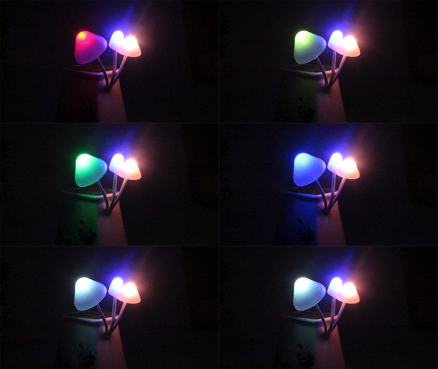
LED Night Light Factory Description: LED has the advantages of high brightness, low power consumption, long life and small size. The night light made with LED is very suitable for home use.
First, the circuit and principle
The circuit uses a capacitor buck bridge rectifier circuit. The voltage reduction is achieved by the capacitive reactance generated by the capacitor C1 in the AC circuit. It is completely different from the resistor buck. In the AC circuit, the capacitor C is used to step down. The capacitor C1 does not consume active power, which is conducive to power saving. Another advantage of the capacitor step-down is that a power transformer can be omitted in the case of low-power applications, which is advantageous for reducing the size of the electrical device and reducing the manufacturing cost. However, the capacitor step-down also has its shortcomings. Its input and output cannot be isolated by the coil windings like the power transformer, so the output is charged, especially in the case of no-load or load-opening, the output voltage is often high. Don’t just touch it with your hands. Pay attention and take some insulation measures during production. Another disadvantage of the capacitor step-down is that the internal resistance of the power supply is very high, and the power quality is poor. In addition, due to manufacturing technology and cost reasons, the current capacity is large, the withstand voltage is high, and the capacitor with a small rest is small, so the capacitor The output current of the step-down is limited, and it should not be used on equipment with high power load variation and high power output accuracy requirements.
C1 is a step-down capacitor, and R1 is a bleeder resistor of Cl, which can be selected according to the size of C1 (generally between 200k and 1MΩ). C2 is a filter capacitor, which is mainly used to smooth DC and absorb (filter) the spike voltage of the power supply, prevent the LED from being broken down, and eliminate the phenomenon of illuminating and flickering. For this reason, C2 should select a small electrolytic capacitor ≥20uF/25V.
D5 is a 10V Zener diode. When the power supply voltage rises, the voltage at the two ends of the load LED will also rise slightly. Because the LED is a device with poor overload capability, it is necessary to make the night light really “long life”. Use a Zener diode to “regulate” to 10V.
Second, component selection and debugging
When purchasing an LED, be sure to ask the true working voltage and working current of the LED, and observe whether the white light emitted by the specified voltage and current is bright (from the top of the tube (the eyes do not stay, otherwise the eyes are There are some damages. Some of the parameters of the pipe are very discrete, such as its forward and reverse resistance. The deviation of the current value of the LED is large under standard voltage. If it is cheap, use this type of pipe [except for single use). Moreover, if multiple tubes are required in series, it is necessary to connect an appropriate and equal “leveling resistor” in parallel with each LED. A relatively close standard beam meter indicates C1. For this reason, the lifting effect of C2 on the rectified voltage in Figure 1 is ignored. Many complicated factors in the case of AC are ignored. The variable is DC, and the initial value of C1 is obtained first. Corrected by experiment.
Three LEDs are connected in series as the load (ie, the night light source). Since the operating voltage of each LED is determined to be VLED=3.3V when purchased, the working current ILED=218~20mA. For safety reasons, the lower limit is 18mA. (Experiments show that the brightness of the LED is basically constant when the operating current of the LED changes from 16 to 20 mA). This requires the capacitor buck rectification source to supply 10V operating voltage (3.3V × 3) and 18mA operating current to the load. Cl takes 0.27uF and has a withstand voltage of 400V.
Because there is no capacitor of this specification, we have to temporarily select 0.33uF/400V as the C1 for circuit experiment.
According to the figure, solder the components and carefully check them before commissioning: 4 In the position shown in the figure, insert a multimeter DB (ie, milliamp, first and then small) and potentiometer with RP=500Ω ( First adjust to the middle value); 2 close the power switch to turn on the mains power; 3 observe the current meter indication value and led lighting situation, if the current meter indication value is only a few milliamps, the LED of course does not light, can adjust the RP resistance The value is rotated in a small direction to increase the current meter indication value. (Conversely, turning in the direction of large resistance) When the RP is adjusted to the normal steady lighting state of the LED, and the current meter indication value is 18 mA, the debugging ends. Remove the ammeter and potentiometer, and measure the resistance of the RP with a multimeter. Replace the series with an equivalent resistor (as a current limiting resistor). When it is found that the resistance of “RP” has been adjusted to “0”, the current is still not up, for example, only 12 mA, indicating that the capacitance of C1 is too large, that is, the capacity of C1 is too small, and it is necessary to increase a capacitor in parallel (note the withstand voltage value). It can be estimated at 5 mA per 0.1 μF increase or decrease. Note that for the safety of the Cl capacity, it is still necessary to serialize the potentiometer RP for the above-mentioned method for debugging. The actual test shows that when C1=0.33uF, even if “RP” is adjusted to “O”, the indication value of the ammeter is only 18.6mA, which is ideal, so it is not necessary to string current limiting resistor. At this time, the measured V4 = 9.3V. There is a 0.7V difference from 10V. 0.7V can be regarded as a safe margin. Even when the input voltage of ~220V rises to ~230V, its output terminal V4 will not exceed 10V. Moreover, there is a 10V regulator tube “clamp” to check it off!
If the night light is calculated according to 0, 3W, even if it is used continuously for 24 hours, 24 hours a day, it is only about one kilowatt hour. It is completely in line with the current energy-saving requirements of promoting “green” lighting in China.
https://www.nhhx.net
