Linsheng -Intelligent Fire Emergency Light Design Structure
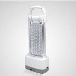
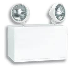
Common intelligent fire emergency light
Since the 1940s, national and local authorities have explicitly stated the use of emergency lights in commercial buildings, industrial facilities and public places to ensure that people are protected from life caused by panic caused by fire or other accidents. The threat of property security. Emergency lights are widely used in large-scale places such as bank business halls, shopping malls and other places where population is concentrated, so as to effectively ensure the safety of out-of-town personnel.
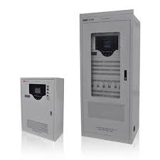
At present, emergency lights on the market are divided into emergency power supply modes: self-contained power supply and centralized power supply. Self-contained power supply comes with a spare battery, which is usually powered by the mains. Only when the mains supply is cut off, the backup power supply is automatically put into operation; the centralized power supply type does not have its own power supply, and when the mains fails, it is powered by a dedicated centralized emergency power supply. .
Working principle of self-contained power type intelligent fire emergency luminaire
Self-contained power supply fire emergency luminaires are mainly composed of the following components: emergency luminaires, batteries, control circuits, status indicators, test switches, etc. For the commonly used emergency evacuation sign lights and emergency evacuation lights, they also have great differences in the choice of these components due to the diversity of application requirements. linsheng briefly describes the device composition and working principle of the two emergency luminaries.
The working principle of the commonly used emergency evacuation sign lamp: If the mains voltage is normal, the status indicator green light, the charging status light (red light) is on, the fault indicator is off, the control circuit controls the switching power supply to supply power to the LED light, and the evacuation display is normal. At the same time, the control circuit detects the mains voltage, the battery voltage and the light source, and provides a charging circuit to charge the battery slowly; if the slow charging is completed, the charging indicator is turned off. If the battery is open, the battery is short-circuited, etc. under normal conditions, the fault indicator (yellow light) is on, prompting the management personnel to check and repair the system; when the mains voltage is lower than the emergency conversion voltage, the control circuit Turn into the emergency state, at this time, the same way of the backup power source and the light source is turned on to ensure that the light source can be normally operated; when the battery voltage is lower than the specified discharge voltage, the control circuit should disconnect all the discharge circuits of the battery, and the entire control The circuit should stop working to avoid leakage of the battery.
The working principle of the emergency evacuation lighting is similar to that of the Changming emergency evacuation lamp. The difference is that under normal conditions of the mains, the light source is not bright. The emergency evacuation lighting should be able to detect whether the light source is open or not. If there is a fault, the indicator light should be on.
The overall structure of the intelligent fire emergency light design
System hardware design
The system is mainly composed of a main controller and an emergency light unit. The main control uses the MCS-51 single-chip microcomputer as the microprocessor, and the emergency light unit also uses the MCS-51 series single-chip microcomputer as the microprocessor. The main controller and the emergency light unit together constitute a multi-microcomputer communication system, and the embedded single-chip microcomputer mainly completes the function of collecting the emergency light state, lighting or extinguishing the emergency light, and communicates with the main controller. The status of the emergency light is sent to the upper main controller in time and displayed on the main controller. If it is a fault state, the main controller will display corresponding sound and light.
Emergency light unit
The emergency light status mainly includes emergency light emergency status, fault status, charging and main power status. The state collection of the emergency light is completed by the single chip microcomputer. Three LEDs are used to indicate the four states of the emergency light, while leaving the serial communication port and the main controller to communicate. This design mainly completes the design of the emergency light unit.
https://www.linsheng.com