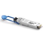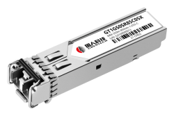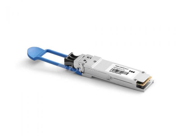
QSFP+ 40G LR4 2KM
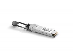
The QSFP+ 40G-LR4-2km module is a highly integrated 4x10G transceiver focused on reach, bandwidth, density and cost for high port-count 40G systems, and client-side 40G interfaces. The 40G QSFP+ LR4 Lite transceiver is designed for applications based on the IEEE802.3ba 40GBASE-LR4 standard of up to 2km reach.
Features of QSFP+ 40G LR4 2km
l Reach: 2 km via SMF
l Uncooled CWDM DFB lasers, directly modulated
l Using ITU G.694.2 wavelength grid at 1271, 1291, 1311, and 1331nm
l User controllable Transmit Input Equalization and Receiver Output Amplitude
l MSA-compliant performance monitoring via I2C interface
l Fiber connector: SMF LC duplex connector
l Compliant with QDR/DDR InfiniBand data rates
l Hot-pluggable electrical interface
l 0–70°C operating temp
l Power dissipation < 3.5W
l RoHS6 compliant (lead-free)
Applications of QSFP+ 40G LR4 2km
l 40G Ethernet
l InfiniBand QDR and DDR interconnects
Specifications of QSFP+ 40G LR4 2km
Optical Transmitter Performance|Optical Receiver Performance|Recommended Operating Environment
Parameter
Symbol
Min
Typical
Max
Unit
Center Wavelength
Ch0
λ0
1264.5
–
1277.5
nm
Ch1
λ1
1284.5
–
1297.5
nm
Ch2
λ2
1304.5
–
1317.5
nm
Ch3
λ3
1324.5
–
1337.5
nm
Bit Rate per Channel
B
10.3125
–
–
Gb/s
Total Average Launch Power
POUT
–
–
8.0
dBm
Side Mode Suppression Ratio
SMSR
30
–
–
dB
Average launch power, each lane
-6.8
–
2.0
dBm
Optical Modulation Amplitude (each lane)
OMA
-6.0
–
3.5
dBm
Optical Modulation Amplitude (OMA) – TDP, per lane (min)
-7.8
–
dBm
Transmission & dispersion penalty,
each lane
TDP
–
–
2.3
dB
RIN12 OMA
–
–
–
-128
dB/Hz
Transmitter Reflectance
–
–
–
-12
dB
Extinction Ratio
ER
3.5
–
–
dB
Transmitter eye mask definition {X1, X2, X3, Y1, Y2, Y3}
{0.25, 0.4, 0.45, 0.25, 0.28, 0.4}
Average launch power of OFF transmitter, each lane
–
–
–
-30
dBm
Optical return loss tolerance
–
–
–
20
dB
Pin Descriptions of QSFP+ 40G LR4 2km
Pin Definition of QSFP+ 40G LR4 2km
Pin
Symbol
Name/Description
1
GND
Ground
2
Tx2n
Transmitter Inverted Data Input
3
Tx2p
Transmitter Non-Inverted Data Input
4
GND
Ground
5
Tx4n
Transmitter Inverted Data Input
6
Tx4p
Transmitter Non-Inverted Data Input
7
GND
Ground
8
ModSelL
Module Select
9
ResetL
Module Reset
10
Vcc Rx
+3.3 V Power supply receiver
11
SCL
2-wire serial interface clock
12
SDA
2-wire serial interface data
13
GND
Ground
14
Rx3p
Receiver Non-Inverted Data Output
15
Rx3n
Receiver Inverted Data Output
16
GND
Ground
17
Rx1p
Receiver Non-Inverted Data Output
18
Rx1n
Receiver Inverted Data Output
19
GND
Ground
20
GND
Ground
21
Rx2n
Receiver Inverted Data Output
22
Rx2p
Receiver Non-Inverted Data Output
23
GND
Ground
24
Rx4n
Receiver Inverted Data Output
25
Rx4p
Receiver Non-Inverted Data Output
26
GND
Ground
27
ModPrsL
Module Present
28
IntL
Interrupt
29
Vcc Tx
+3.3 V Power supply transmitter
30
Vcc1
+3.3 V Power Supply
31
LPMode
Low Power Mode
32
GND
Ground
33
Tx3p
Transmitter Non-Inverted Data Input
34
Tx3n
Transmitter Inverted Data Input
35
GND
Ground
36
Tx1p
Transmitter Non-Inverted Data Input
37
Tx1n
Transmitter Inverted Data Input
38
GND
Ground
Important Notice of QSFP+ 40G LR4 2km
Performance figures, data and any illustrative material provided in this data sheet are typical and must be specifically confirmed in writing by T&S before they become applicable to any particular order or contract. In accordance with the T&S policy of continuous improvement specifications may change without notice.
The publication of information in this data sheet does not imply freedom from patent or other protective rights of T&S or others. Further details are available from any T&S sales representative.